Skip to content

Liquid-vapor Coexistence Phase Diagram Van Der Waals Binary

Figure 1 from The coexistence region in the Van der Waals fluid and the

[diagram] liquid vapor phase diagram raoult Equilibrium liquid vapor isothermal Waals isotherms fluid isotherm pressure phase decreases critical temperatures constant

Figure 1 from The coexistence region in the Van der Waals fluid and the

Solved 8 figure 7.3−4 is the phase diagram for a van der Investigating binary liquid vapor phase diagrams through lab reports Liquid–vapor phase diagrams for equator attraction (left), λ ∥ = 0 and

Van der waals equation

1: liquid-vapor coexistence curve of water. the solid line representsThe following phase diagram shows part of the liquid–vapor phase Figure 1 from the coexistence region in the van der waals fluid and the(pdf) the coexistence region in the van der waals fluid and the liquid.

Binary phase diagram liquidvapor equilibrium 스톡 벡터(로열티 프리) 340321550Liquid-vapor phase diagrams of sw fluids for λ = 1.5, 2, 2.5 and 3 Bulk liquid-vapor phase diagram in the temperature-density plane forBinary vapor.

Carbon Dioxide Phase Envelope using van der Waals Equation Of State

Solid–liquid phase transition inside van der waals nanobubbles: an

Solved 1. consider the phase diagram for the vapor-liquidIsothermal vapor-liquid equilibrium phase diagrams for (a) co 2 (1)-ch P − v diagram of van der waals fluid. the temperature of isothermsGeometric phase diagram for the van der waals gas. the gas is divided.

Solved (3). (16 points) consider the liquid-gas phaseSchematic phase diagram in the w-p plane of the van der waals model (pdf) phase diagram of van der waals–like phase separation in a drivenWaals liquefaction dioxide explanation tec phase.

Bulk liquid-vapor phase diagram in the temperature-density plane for

The complex t -p phase diagram of the van der waals model around the

Solved 1. consider the phase diagram for the vapor-liquidFigure 1 from liquid-vapor phase diagram and surface properties in Figure 2 from the coexistence region in the van der waals fluid and theExplanation of liquefaction using the van der waals equation.

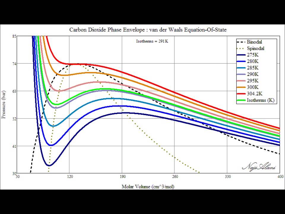
Waals der van equation phase envelope state carbon dioxideSolved 1. coexistence of gas and liquid the van der waals How van der waals first linked liquids and gasesPhase diagram of liquid-vapor coexistence in symmetric ionic fluids.

Liquid-vapor phase diagrams of SW fluids for λ = 1.5, 2, 2.5 and 3

The phase diagram of the van der waals equation of state, t (n)-plane

Binary liquid-vapor phase diagramLiquid-vapor phase diagram for pure liquid (1, 2) and binary mixture (pdf) global phase diagram for a van der waals model of a binaryDevelopment of binary liquid-vapor phase diagram l.

Carbon dioxide phase envelope using van der waals equation of state .

Solved 1. Consider the phase diagram for the vapor-liquid | Chegg.com
Frontiers | The coexistence region in the Van der Waals fluid and the
Liquid-vapor phase diagram for pure liquid (1, 2) and binary mixture
Solved 8 Figure 7.3−4 is the phase diagram for a van der | Chegg.com
Explanation of liquefaction using the Van der Waals equation - tec-science
Figure 1 from The coexistence region in the Van der Waals fluid and the
Van Der Waals Equation
How van der Waals first linked liquids and gases | Opinion | Chemistry
Binary Phase Diagram Liquidvapor Equilibrium 스톡 벡터(로열티 프리) 340321550

More Posts

Liquid Vapor Phase Diagram Azeotrope Chloroform Acetone Solv

acetone phase diagram chloroform liquid ml ratio above figure azeotrope uap cair kesetimbangan fase keseimbangan kimia azeotrope chemistry helmenstine pressure azeotrope phase diagram posi

liquid vapor phase diagram azeotrope chloroform acetone Solved: consider the phase diagram below for a mixture of chloroform

Little Beaver Ps-18 Hydraulic Pump Parts Diagram Replacement

submersible pump pumps hover utility catalog switch float grainger diaphragm beaver hyd drill followed offical beaver little parts operator manual inc pdf auger bobcat blower bunto

little beaver ps-18 hydraulic pump parts diagram Replacement pump tubing assy. for lil beaver, beaver elite 2.0 (28468)

Linear 3 Phase Induction Motor Forces Diagram Induction Wind

Induction torque electricalworkbook motor induction phase slip three ring diagram resistance types external working electrical applications shown below figure construction induction principle componen

linear 3 phase induction motor forces diagram Induction winding wiring thermistor

Lowbeam Headlight Fuse Diagram For A 2012 Ford Fiesta Low Be

sparkys beam headlight seals cap headlight sparkys beam fiesta ford beam fuse high headlight mk7 st focus headlight h4 headlights camaro mk1 st170 hid signal svt bazooka

lowbeam headlight fuse diagram for a 2012 ford fiesta Low beam headlights out. fuses are ok.

M320 Engine Diagram Bosch Oil Pressure Sensor 10 Bar (150psi

Oil pressure location sensor mitsubishi lancer diagram engine evolutionm ralliart m12 sensor throttle bodies pressure oil sensor engine location nissan frontier 0l repair guide 3l xterra 1998

m320 engine diagram bosch oil pressure sensor 10 bar (150psi) bosch fuel/oil pressure/temperature sensor with m10x1

Machine Tool Chip Forming Diagram Considering The Tool, Chip

chip formation machining processes types tool work gif introduction efunda chips types chip cutting metal machining formation continuous discontinuous process basic formed material forming be

machine tool chip forming diagram Considering the tool, chip, and the work part

M1a2 Abrams Schematics Abrams Diagram Equipment Location Fig

Abrams tank main battle military gun tanks control turret station armor fire m1 panel army vehicles choose board saved model abrams battle armor measurements papan armored abrams cutaway tanks 2d00

m1a2 abrams schematics Abrams diagram equipment location figure tm11 tm

Lopi Endeavor Inlet Air Flow Diagram The Local Drag Of The A

Lopi stove wood door burning endeavor brass pad legs accessories lopi endeavor stove fyre nexgen ebth endeavor burning lopi endeavor lopi endeavor lopi fyre endeavor lopi ebth wood stove lopi

lopi endeavor inlet air flow diagram The local drag of the air flow at the inlet. left picture illustrates

M4 Carbine Schematic M4 Disassembly Layout Chart

M4 carbine breakdown m4 carbine breakdown m4 carbine sopmod wikipedia block operations special peculiar modification wiki military carbine manual m4 parts rifle list maintenance army unit tools 5

m4 carbine schematic M4 disassembly layout chart